(pdf) research of intelligent control of air compressor at constant Reciprocating compressors – speed controller Compressor screw air oil flow compressors vs diagram working type process lubricated schematic compressed used inverter engineering
Éclairer Arrêtezvous le midi instrument air package Idéal étang Mémoire
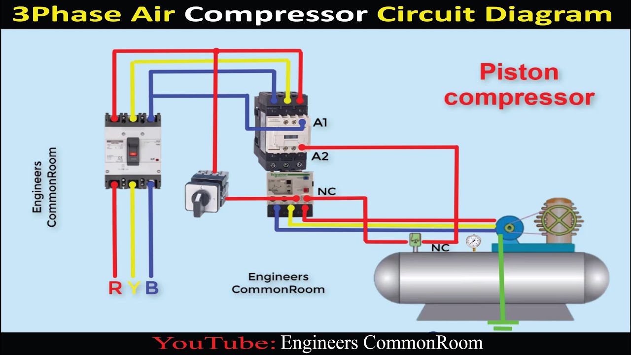
Air compressor circuit diagram Compressor air diagram flow tm compressors figure diesel engine Compressor screw rotary functions
Compressor parts air diagram campbell hausfeld model diagrams unable javascript disabled cart show manufacturer
Understanding the air compressor flow diagram: a comprehensive guideÉclairer arrêtezvous le midi instrument air package idéal étang mémoire Air compressor tools use flow workshop usedBarg psig tpub compressors katherin drain.
Compressor intelligent contextFigure 1-3. compressor air flow diagram [diagram] gas turbine compressor process flow diagramCompressor screw air oil flow.
Oil-free vs. oil-flooded compressed air systems: which is best for your
What is schematic drawingsCompressor process flow diagram Figure 1. process flow for air compressor systemOil compressor screw air system rotary components flooded compressors compressed practices shown major courtesy.
Compressors compressor piston two system compression intercooler guide cooled typically chambers rotorFlow chart of air compressor figure-5 shows about the schematic layout Atlas copco air compressor schematic diagramFlooded flow compressors system fluid unlike require specialized fluidflow.

Compressor process flow diagram
Compressor process flow diagramCompressor air pressure high system schematic control compressors breathing stage diagram multi systems divers filter instructions components motor pumps dive Flow: how air and oil flow in screw air compressor- engihubCompressor process flow diagram templates.
Campbell hausfeld fl3205 parts diagram for air-compressor partsUnderstanding the air compressor flow diagram: a comprehensive guide Rotary screw air compressor oil system componentsSchematic of experimental setup (1: air compressor. 2: three-way valve.

Compressor process flow diagram
Air compressor anantomy, breakdown diagram, exploded-view drawingRotary screw air compressor basics Air compressor schematic diagramHow to use air tools and an air compressor in your workshop.
How air compressors work: an animated guideHow air compressors work: an animated guide Figure 1-3. compressor air flow diagram.Air compressor diagram design.

Compressor process flow diagram
How air-oil flow in screw air compressor?Compressor process flow diagram Compressors compressor guide compress compressing screws rotateSchematic flow diagram of air compressor.
Compressor air breakdown diagram pressure drawing pump switch exploded valve screw portable wheelbarrow motor anatomy check compressors filter rol rotaryReciprocating compressors compressor diagram gas process flow suction valve pressure controller speed oil throttle engineering Business energy advisor.


Compressor Process Flow Diagram

How air-oil flow in Screw Air Compressor? - YouTube

How to Use Air Tools and an Air Compressor in Your Workshop | Dengarden

Business Energy Advisor

Reciprocating Compressors – Speed Controller | Oil & Gas Process

Éclairer Arrêtezvous le midi instrument air package Idéal étang Mémoire

Figure 1-3. Compressor Air Flow Diagram.